Introduction
Over many years of designing communication networks and network security architectures, I have consistently found that a structured, methodical planning process is the single most important factor in project success. A disciplined approach prevents unnecessary costs, avoids technical failures, and delivers a network that genuinely meets the organization’s needs — no more and no less.
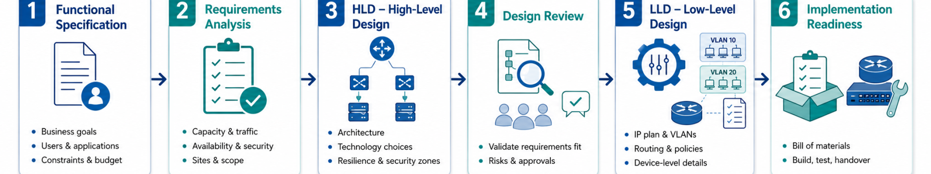
This article walks through the three main phases of network planning:
- Phase 1: Functional Specifications: define what we need the network to do
- Phase 2: High-Level Design (HLD): the architectural blueprint
- Phase 3: Low-Level Design (LLD): the complete implementation specification
For each phase, we cover what activities take place, what decisions are made, and what deliverables must result. The framework applies equally to server infrastructure, software, and information security projects, not just networks.
| About this series
This article focuses on the design process. Future articles in the series will cover financial planning and budgeting, procurement of best practices and vendor management, and end-to-end project execution. |
Planning Phases Overview
Like any engineering discipline, data network and information security planning follows three core phases:
| Phase | Name | Key Question Answered | Primary Author |
| 1 | Functional Specifications | What do we need? | Organization only |
| 2 | High Level Design (HLD) | How will it work architecturally? | Organization or Vendor |
| 3 | Low Level Design (LLD) | Exactly how do we build it? | Vendor (reviewed by Org) |
It is worth noting that a single body does not formally standardize this planning methodology. Different vendors, Cisco being a well-known example, define design phases and document types in slightly different ways. Thousands of design templates are freely available from vendors and via web search. The framework here reflects best practices accumulated across many real-world projects.
Phase 1: Functional Specifications
The purpose of functional planning is to translate business requirements into precise technical requirements — in plain terms, to define exactly what we need.
1.1 Defining Project Goals
A functional specification begins by articulating why the project exists. Examples of project goals:
- Improve application performance across the network
- Achieve cost savings in communication infrastructure
- Comply with specific information security regulations
- Replace end-of-life equipment before vendor support ends (EOL/EOS)
- Segregate IT and OT (Operational Technology) networks per regulatory mandate
1.2 Organizing Requirements by Category
A structured way to ensure no requirement is missed is to organize functional requirements into standard categories. Use the table below as a checklist when preparing the Functional Specification document:
| Category | Typical Questions to Answer |
| Availability & Resilience | What uptime is required? What is the maximum tolerable downtime? Is Five Nines required? |
| Security & Compliance | Which regulations apply (GDPR, SOC 2, ISO 27001, sector-specific)? What data classifications exist? |
| Performance & Capacity | What bandwidth/throughput is needed today and in 3–5 years? What latency targets exist per application? |
| Scalability & Growth | What growth rate is anticipated? How many new sites, users, or devices in 3 years? |
| Manageability & Observability | Who manages the network? What monitoring tools exist? Is NOC or SOC involved? |
| Budget & TCO | What is the CapEx budget? What OpEx can the organization sustain? What is the expected asset lifecycle? |
| ✓ Stakeholder Sign-Off Before Proceeding
Have the completed Functional Specification formally reviewed and signed off by both technical and business stakeholders before moving to HLD. This single step prevents the majority of costly scope changes that occur later in the project. It also creates a contractual baseline if the work is being procured from an external vendor. |
1.3 Real-World Functional Requirement Examples
The following are genuine examples drawn from projects I have worked on:
- Replacement of network equipment due to End-of-Life (EOL) and End-of-Support (EOS), when the vendor will no longer supply patches or hardware replacements
- Business requirement for high availability: Five Nines uptime (99.999%), no more than 5 minutes of unplanned downtime per year
- Regulatory compliance with the Privacy Protection Authority, requiring separation and protection between data repositories
- High bandwidth demand for a new application being deployed by a software vendor, specific throughput and latency SLAs stated
- Regulatory requirement to segregate IT and OT networks (common in industrial, utilities, and healthcare environments)
- Cost reduction target in communications expenditure, specific percentage or annual saving required
1.4 Greenfield vs. Brownfield
Greenfield design (new network from scratch) and Brownfield design (modifying an existing network) require different planning approaches. The Functional Specification must explicitly state which applies, and in Brownfield cases, must document the existing state of the network in sufficient detail to allow the designer to understand constraints and dependencies.
1.5 Who Prepares the Functional Specification?
The Functional Specification must always be prepared by the organization itself. Only the organization knows its business processes, risk tolerance, regulatory obligations, and operational constraints. External consultants can facilitate and advise, but the organization must own and validate every requirement.
| ⚠ Do Not Skip This Phase
Skipping or rushing the Functional Specification is the leading cause of cost overruns and scope disputes in network projects. Every hour invested here saves days during implementation. The examples in the Procurement section of this article illustrate how dramatically project scope changes once requirements are properly understood. |
Phase 2: High Level Design (HLD)
Once the Functional Specification is agreed, we know what must be addressed. The HLD defines how the network will work at an architectural level including the topology, technology choices, security posture, and design principles that will govern the detailed design.
The HLD document typically includes written documentation, Visio (or equivalent) diagrams, and tables. Content varies by project but commonly covers:
2.1 System Components
- All required network and system components: switches, routers, firewalls, servers, load balancers, etc.
- Example: the management system will run on a dedicated server installed at the network core
- Example: Central FWs will protect the Data Center; separate FWs will protect the Internet egress point
- Example: Central FWs will run FW + IDPS; Internet egress FWs will run full UTM (web filtering, AV, IPS, etc.)
2.2 Network Topology and Component Placement
- Conceptual network diagram (Visio or equivalent) showing all major components and their relationships
- Router placement, redundancy scheme (HSRP, VRRP, or equivalent), recommended routing protocols, and required failover convergence times
- VLAN structure (logical groupings, without VLAN IDs at this stage), inter-VLAN routing policy (which VLANs route to each other, which are isolated)
- WAN/Internet connectivity: link types, redundancy, provider diversity
2.3 Protocol Selection and Rationale
The HLD must specify which protocols will be used and, critically, why. This rationale is especially important when the document is shared with vendors for independent review or used as a basis for tendering.
- Example: OSPF will run on internal networks; separate VRFs will be defined for administrative and operational network segments; PIM will be configured for multicast distribution of classified data feeds
- Example: Layer-7 inspection will be enforced on the central FWs for traffic involving classified data repositories; general business traffic will use a separate path via core switches to avoid unnecessary latency
2.4 Security Architecture
- Firewall placement and zone model (Internet, DMZ, Internal, OT, Management)
- Network Access Control (NAC) approach if applicable
- Remote access architecture (VPN type, MFA requirements, split-tunnel policy)
- Segmentation strategy for regulatory compliance (e.g., PCI DSS cardholder data environment isolation, IT/OT separation)
2.5 Additional HLD Topics
| HLD Completeness Checklist
The following topics are frequently addressed at HLD level. Not all apply to every project; you should mark those relevant to your scope: • IP addressing plan (summary level – subnet allocations, not individual addresses) • QoS / traffic prioritization strategy (especially for voice, video, or real-time OT traffic) • Out-of-band (OOB) management approach: how will devices be accessed if the production network is down? • Monitoring and alerting architecture – SNMP/NetFlow/syslog strategy, SIEM integration • Change management approach and maintenance window policy • Disaster Recovery architecture and RTO/RPO targets • Physical security requirements (locked cabinets, access control to comms rooms) • Environmental requirements (power, UPS, cooling) if relevant to scope |
2.6 Regulatory and Framework Alignment
Where the project is driven by compliance requirements, HLD should explicitly reference the relevant framework and demonstrate how the design addresses its controls:
- ISO/IEC 27001 Annex A controls for network security (A.8.20–A.8.22), access control (A.8.3), and cryptography (A.8.24)
- NIST SP 800-53 SC (System and Communications Protection) and AC (Access Control) control families
- NIST CSF maps the design to Identify / Protect / Detect / Respond / Recover functions
- PCI DSS v4 network segmentation requirements for cardholder data environments
- TOGAF for organizations requiring formal enterprise architecture alignment
| ✓ Referencing a Recognized Framework
Aligning the HLD to a recognized framework (even partially) adds credibility with regulators and auditors, simplifies gap analysis, and makes the document more useful as a long-term reference. It does not require full certification – referencing the relevant controls is sufficient. |
2.7 Who Prepares the HLD?
This is a nuanced topic with two main approaches:
Option A – Vendor Prepares the HLD
The organization provides the Functional Specification and requires the vendor (or the winning bidder in a tender) to produce the HLD. The organization specifies performance requirements, failover times under 50ms, specific throughput, delay, jitter, and packet loss parameters, and the vendor must design to meet them.
- Advantage: the vendor bears full responsibility for meeting the stated requirements
- Disadvantage: the organization must carefully validate that the solution meets requirements without unnecessary over-engineering
Option B – Organization Prepares the HLD
The organization produces the HLD itself and requires vendors to propose solutions that comply with it. Some flexibility can be offered, for example, permitting two alternative topologies or specifying protocol families rather than exact protocols.
- Advantage: vendor proposals are directly comparable; the organization controls the design
- Disadvantage: vendors may later disclaim responsibility for issues in a design they did not author
The Practical Middle Ground
In practice, a hybrid approach often works best: issue a Request for Information (RFI) with a preliminary design outline to gather vendor input, then finalize the HLD incorporating relevant feedback before issuing the formal Request for Proposal (RFP) or tender. This approach benefits from vendor expertise while keeping the organization in control of the design direction.
In the following figure, you can see an example for a network design in the HLD level.
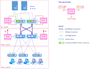
The diagram above shows a representative HLD network topology, including proposed firewall placement, interface bandwidth allocations, Layer 3 VLAN boundaries, and server connectivity. With these architectural decisions established, the project is ready to progress to the Low Level Design phase.
Phase 3: Low Level Design (LLD)
The LLD is the complete technical blueprint for building, configuring, and commissioning the network. It covers everything from procurement through acceptance testing. The standard definition:
A qualified network engineer must be able to take the LLD document and, without any additional documentation, install, configure, and operate the entire system.
3.1 LLD Content Areas
Server and Virtualization Specifications
- Full server inventory: server name, role, IP address, VLAN assignment, installed services and software, primary/standby designation
- VM placement: which ESXi (or Hyper-V / KVM) host each VM runs on, resource allocations, HA/DRS policy
Network Design Detail
- Complete VLAN design with VLAN IDs, names, descriptions, and port assignments
- Full IP addressing tables for all interfaces, loopbacks, management addresses, and DHCP ranges
- Routing tables and protocol configurations (OSPF area assignments, BGP peer groups, static routes, redistribution policies)
- ACL definitions, placement, and directionality (inbound/outbound per interface)
- Flow diagrams: unicast and multicast traffic flows with VLAN numbers and addresses
Information Security Detail
- Complete Firewall rule bases, all rules with source, destination, service, action, and logging policy
- Security policy/communication matrix – who may communicate with whom, using which applications, at which times
- IDS/IPS policy definitions: signature groups, alert thresholds, inline vs. passive mode per segment
- Full configuration files for all network devices (may be included in the LLD itself or delivered as a separate but linked configuration package)
Hardware and Software Bill of Materials
- Complete BOM with part numbers, software versions, and quantities for all components
- Inter-component connection diagrams (physical cabling, SFP types, interface numbers)
3.2 The LLD Completeness Checklist
Use the following checklist when reviewing an LLD before accepting it from a vendor or before submitting it for CDR approval:
| LLD Section | Included? | Notes |
| Server inventory (name, role, IP, VLAN, primary/standby) | ||
| VM placement per ESXi host | ||
| VLAN design with VLAN IDs and descriptions | ||
| IP addressing tables (all interfaces and loopbacks) | ||
| Routing tables and protocol configurations (OSPF areas, BGP peers, etc.) | ||
| ACL definitions and placement | ||
| Firewall rule bases (complete) | ||
| Security policy/communication matrix | ||
| NTP architecture and time sources | ||
| Syslog / SNMP destinations and alert thresholds | ||
| Certificate management (PKI, expiry schedule) | ||
| Backup and restore procedures per device type | ||
| Cable plant documentation (patch panels, label convention) | ||
| IPAM integration / IP allocation records | ||
| Full configuration files (show run) or reference to separate config package | ||
| Inter-system and intra-system data flow diagrams | ||
| Hardware/software BOM with part numbers and versions |
| ✓ Configuration Files and the LLD
Configuration files (show run output or equivalent) may be delivered as part of the LLD document or as a separate, referenced configuration package. Either approach is acceptable provided the LLD precisely defines every parameter needed. In practice, some configuration refinements always occur during commissioning – the LLD should be updated to reflect the as-built state before handover. |
The table below is an excerpt from a real-world LLD address table, condensed here for illustration, as it was originally part of a significantly larger project.
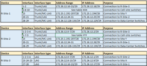
This table, together with its accompanying diagrams, gives the installing engineer a precise and unambiguous address plan, with no interpretation required. Taking the first entry (R-Site-1) as an example, the table specifies each router interface, LAG and MC-LAG assignments, trunk port definitions, subnet ranges, individual addresses, and descriptive notes. A complete LLD will include equivalent tables for every device in the network.
Additional Processes and Project Milestones
A properly structured project includes several formal checkpoints beyond the three design phases. These are not bureaucratic overhead – they are quality gates that protect both the organization and the vendor.
4.1 Proof of Concept (POC)
For projects with unique, high-risk, or first-time requirements, a POC should be requested before committing to full procurement. The POC validates that the proposed solution meets the stated requirements in a controlled environment. For mission-critical or highly complex projects, a POC is strongly recommended even if it adds time and cost, it almost always reveals integration issues that would be far more expensive to resolve in production.
4.2 Pilot
A pilot (sometimes structured as a first and second pilot) allows gradual rollout of the project. A pilot typically covers a single department, floor, or branch office, testing specific capabilities before organization-wide deployment. The scope and criteria for the pilot should be defined in the project plan, not improvised during implementation.
4.3 Acceptance Test Plan (ATP)
At project conclusion, a formal ATP must be executed before final payment is released and the project is signed off. The ATP verifies that the deployed project meets the requirements and includes:
- Sanity / Go–No-Go tests: basic connectivity, device reachability, management access
- Functional tests: redundancy failover (measure actual convergence time), VLAN isolation, firewall policy enforcement, VPN connectivity
- Performance tests: throughput under sustained load, latency per traffic class, packet loss at rated capacity
- Security tests: penetration test or vulnerability scan of the new network perimeter; validation of FW rule base against the approved policy
| ⚠ Agree on ATP Criteria Before the Project Begins
The ATP document should be prepared, agreed upon, and signed by both parties before the project starts, not after delivery. Agreeing on acceptance criteria upfront removes ambiguity at handover, prevents disputes about what ‘working’ means, and creates a legally clear basis for payment milestones. |
4.4 Formal Design Review Gates
In structured project management, formal design review gates are used to control progression between phases:
- Preliminary Design Review (PDR): the HLD is presented to stakeholders for review and formal approval. No LLD work begins until the PDR is passed.
- Critical Design Review (CDR): the completed LLD is presented for final approval before any procurement or implementation begins. This is the last point at which design changes can be made without significant cost impact.
| ✓ Treat Design Reviews as Decision Gates
PDR and CDR should have defined approval criteria and must produce a formal sign-off document. ‘Presenting’ a design is not the same as approving it. If a CDR reveals gaps in the LLD, the LLD must be corrected and re-reviewed — proceeding to implementation with an incomplete LLD guarantees problems. |
How the Design Process Integrates with Procurement
Procurement is a complex topic that warrants a dedicated article, but several observations from real projects are essential to note here.
5.1 How Scope Changes When Requirements Are Properly Defined
In many projects I have been involved in, once requirements were precisely defined in Phase 1, the project scope changed dramatically from the original assumption. Examples from real engagements:
- A project requiring replacement of dozens of branch routers with firewalls was ultimately resolved by defining ACL policies on the existing equipment, because properly reading the regulatory requirement revealed that FWs were not actually mandated.
- The SD-WAN initiative continued as a conventional router upgrade; that is because the actual traffic patterns and application requirements did not justify the SD-WAN financial overhead.
- A project initially valued at many tens of thousands of dollars was restructured as a basic endpoint security software deployment.
- A cellular network initially scoped with a full MPLS core and BGP-VPN routing was ultimately deployed using OSPF, once the functional requirements were properly reviewed, it became clear that the client needed a simple, maintainable routing solution that could be operated independently by a local team, not a carrier-grade architecture.
The lesson is consistent: define precisely what you need, verify it, consult widely, check again, and avoid spending on capabilities the organization does not actually require. Incorrect licensing, imprecise load estimates, and excessive contingency margins can each individually double project cost.
5.2 Change Control
| ✓ Establish Change Control Before Work Begins
A formal change control process must be defined before the project starts. Key principles: • All changes to scope, design, or requirements must be documented in a Change Request (CR). • Every CR must include an impact assessment: cost, schedule, and technical risk. • Changes identified during Functional Specification are cheap. Changes during HLD are moderate. Changes during LLD or implementation are expensive. Changes during testing are very expensive. • No change is implemented without written approval from the designated authority (project sponsor or steering committee). • The LLD must be updated to reflect all the changes approved. The as-built LLD becomes the network’s operational baseline documentation. |
5.3 RFI, RFP, and RFQ
RFI (Request for Information): issued before tendering to gather market intelligence and vendor input on a preliminary design. Responses are non-binding.
RFP (Request for Proposal): a formal solicitation requiring vendors to propose a complete solution. Responses are evaluated technically and commercially and form the basis of vendor selection.
RFQ (Request for Quotation): used when the design is already complete and defined; vendors are asked only to price a specified bill of materials. Appropriate after a completed LLD.
Summary
Network and security planning done well is not glamorous work, but it is the difference between a project that delivers value and one that delivers problems. The key takeaways:
- Phase 1 (Functional Specifications): define what you precisely need, in writing, organized by category, reviewed and signed off by business and technical stakeholders before any design work begins.
- Phase 2 (HLD): define the architectural approach, including topology, protocols, security posture, framework alignment, without yet descending to device-level configuration detail.
- Phase 3 (LLD): provide a complete implementation blueprint, including everything a certified engineer needs to build, configure, and operate the system without any additional documentation.
- Additional milestones: POC, Pilot, ATP, PDR, and CDR are quality gates, not bureaucratic overhead. Each one exists because projects fail without them.
- Change control: define the change process before work begins. The cost of a change increases by an order of magnitude at each phase boundary.
- Procurement: only procure after requirements are precisely defined. Match the procurement instrument (RFI / RFP / RFQ) to the level of design completeness.
The planning discipline described here applies across the full technology stack — networking, servers, software, and information security. Getting it right at the beginning is always cheaper than fixing it later.
| Next in the Series
The next articles will cover financial planning and budgeting for network projects, including how to build a realistic CapEx and OpEx model, what cost categories are routinely missed, and how to structure the financial case for management approval. |
About the Author
| Yoram Orzach
CTO, NDI Communications, CyberSpark Consulting The author has over 30 years of experience in the design, planning, and implementation of data communication networks and information security architectures. Throughout this time, he has led projects spanning enterprise networks redesigns, data center buildouts, IT/OT network segregation, and regulatory compliance programs across a range of industries. Areas of expertise include network architecture, firewall and security platform design, high-availability network engineering, and vendor evaluation and procurement. Contact / LinkedIn: https://www.linkedin.com/in/yoram-orzach-9434282/ |

